Author Archives: Steve Kemper

Interruptions and Interrupts

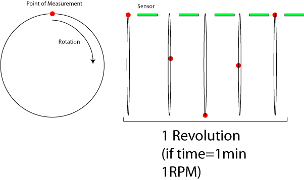
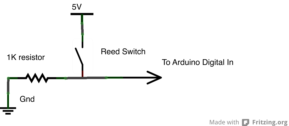
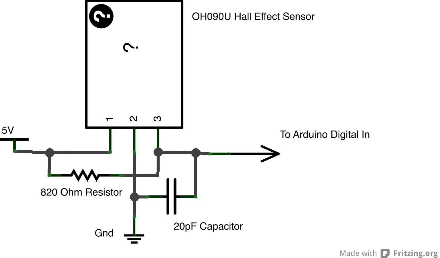
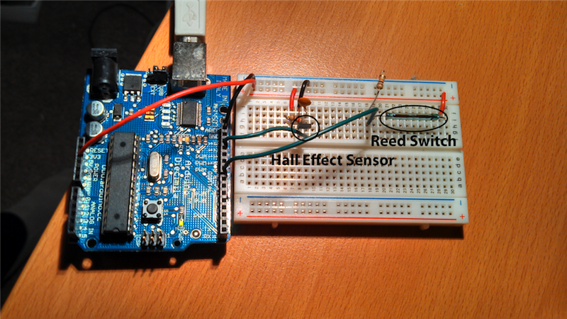
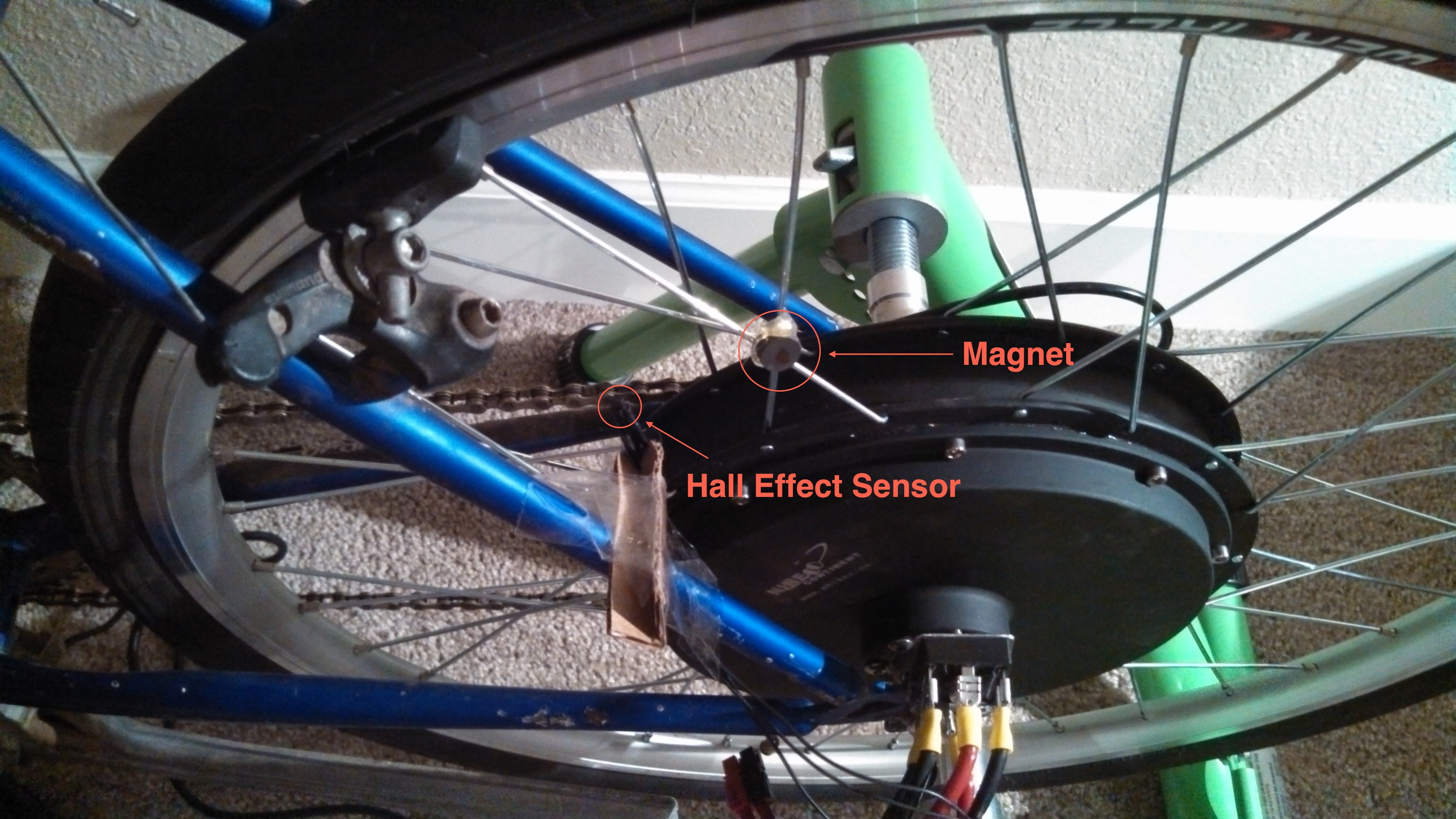
In my earlier post RPMs to BPM, I demoed a fairly simple hall effect circuit that I used to control the playback speed of an audio file in Max. In the video, I wave a magnet in front of the sensor and used the resulting data to trigger a “bang” in max. This method worked fine in my demo as I could not trigger the sensor very quickly. When I hooked the sensor up to the bike, I realized that above a certain rotational speed, the software would “miss” rotations. [I have since switched to using the sensors in the hub motor, but they present the same issues]

2013-04-01 21.30.26

Thus I realized I had a problem. Though the Arduino has no problem catching the incoming sensor data (it typically executes code in the range of microseconds (1 millionth of a second), I was running into trouble passing the data between the Arduino and Max. Without getting too technical, the data transfer speed was too slow.

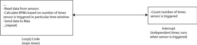
As someone who tries to be primarily concerned with the realization of creative projects rather than elegant technical solutions, I will admit that I always aim for the simplest solution even if it isn’t the most efficient. Sometimes, as in this case, the simplest solution (handling all of my data calculations in Max) just isn’t going to work. I realized I was going to have to calculate RPMs using the Arduino and then transmit a running tally of the current RPMs to Max (along with data from the Force Sensing Resistors, as seen in this video). I knew that this could pose a large technical problem. I would need to calculate the RPMs by taking the triggers from the Hall effect sensors while at the SAME TIME I would need to be constantly updating the data from the Force Sensing Resistors. Typical Arduino sketches have one function–loop(), which runs over and over while the board is on. Pausing to wait for incoming data from the Hall effect sensors would delay the execution of my code and stop the data being sent to Max–I needed to do two things at once.

Fortunately in the world of open source technology, the solutions to many technical challenges lie online. This great example by Zitron shows how to use hardware interrupts to read in the data from the hall effect sensor outside of the loop() function.

Interrupt

The result is that I can just send a constantly updated stream of RPM data to Max. This turns out to be a much better solution, because if I miss a sensor trigger between the Arduino and MAX, the RPM data will be wrong (sometimes VERY wrong). If I miss one read of RPM data, it’s not a big problem because I am constantly sending the current number of RPMs.

The bigger lesson here is that the easiest solutions are always the best, but sometimes an easy solution just wont work. In that case you have to delve deeper. While you don’t want technical complexity to derail your project, sometimes more complex solutions end up being the most elegant.


RPMs to BPM

Well, more like RPMs to playback speed. The video below shows how I’ve hooked up the hall effect sensor to Max in order to control playback speed of a sound file.

Movable Party–Hall Effect Playback Speed Demo from Steven Kemper on Vimeo.

Interactive DJ

Moveable Party will feature traditional DJ sets (bicycle-powered of course) as well as interactive DJing that uses sensors attached to bikes to control parameters of sound production/processing. The goal is to design an interface in Max that mimics those found in traditional DJ software. The interactive DJs will be able to map the sensors on the bike to various modes of sound control. For example, the speed of the rear wheel could control playback speed (as in the example above), or tempo of a step sequencer. Pressure sensors mounted on other parts of the bike, for example the handlebars, could be mapped to a variety of different types of processing, including EQ, Delay, Volume (enveloping), etc.

Rear Wheel Tachometer

One of the goals of Movable Party is to provide an interactive experience for audiences/participants. Since power will be generated from a hub motor attached to the rear wheel of each bike (see this post), the speed of the rear wheel directly translates to the amount of power generated. Detecting how fast the rear wheel is moving thus seems like the most obvious/important piece of data to capture from these stationary, power-generating bikes.

Tachometer
The easiest way to detect the speed of the rear wheel (the way most bike computers work), is to make a tachometer–simply put, a revolution counter. By counting the number of revolutions over a certain period of time, we can determine how fast the wheel is turning. Basically, you want to count the number of times a specific spot on the wheel crosses a point of measurement, and divide by some time constant (e.g. Revolutions per Minute, RPMs). Electronically, you are triggering a switch every time this point on the wheel passes a fixed sensor.

Basic Tachometer Model

Because the wheel is turning and the sensor is fixed, using a mechanical switch where there is contact every rotation will not work very well. For example, the mechanical switch will cause friction every rotation. Also, maintaining perfect distance between the wheel and the switch will be difficult. Instead, there are two common ways of detecting rotation that do not require contact between the sensor and the wheel–optically and magnetically. Due to my own personal familiarity with magnetic circuits, as well as the expense of using an optical system and concerns about the functionality of that system in ambient light, I have decided to pursue magnetic sensing.

Sensing Changes in Magnetic Fields
To construct a tachometer using a magnet, you attach the magnet to the wheel, and attach a sensor to the fork (at a fixed position). As the magnet passes by the sensor, it triggers a switch that allows you to count the number of revolutions over a period of time. There are two types of sensors that accomplish this function: reed switches and Hall effect sensors. The reed switch is a simple switch that is closed (or opened) using a magnet.

Reed Switch Schematic

The Hall effect sensor converts changes in magnetic fields to analog voltage. The mystery of how the Hall effect actually works from a scientific standpoint goes beyond my level of understanding as a musician/tinkerer, but for our purposes the sensor functions like a digital switch. (Fritzing, which I used to make the schematic below does not have a built-in part for a Hall Effect sensor, so I am using the “mystery” part)

Hall Effect Circuit Schematic
Hall Effect Schematic

Testing
I tested both the reed switch (ORD-229-2530) and the Hall effect sensor (OH090U) with two types of magnets: 1/4″x1/16″ N42 neodymium magnet and 1/2″ x 3/16″ Ceramic Disc Magnet. I hooked both up to a simple sketch on the Arduino so I could see when the switches were open/closed. Neither magnet worked very well with the reed switch unless I was basically touching the switch (conclusion: I would need stronger magnets). Both magnets worked with the Hall effect sensor. The neodymium magnet consistently triggered the switch 1/4″ from the sensor and the ceramic magnet worked 3/8″ from the sensor. I am not sure what kind of sensing distance we will need for the rear wheel of the bike, however if these distances are too small, a stronger/larger magnet should work. My fellow Movable Partiers are working on getting their hands on some magnets from reclaimed bike computers, which hopefully will work well.

Breadboarded Hall effect and reed switch circuits
Hall effect and reed switch circuits connected to (a very old) Arduino

Next Steps
The goal of these preliminary tests was to make sure I could actually build the circuit and get it to work. The next step is to hook it up to a bicycle and make sure we can get an accurate count of rotations. The physical connection to the bicycle represents one challenge that should be figured out sooner rather than later. For the electronics, we will probably need to implement some kind of edge detection code on the Arduino to make sure that we only get one “trigger” every time the magnet passes the sensor. Once this has been accomplished, I will need to program a sketch on the Arduino that allows us to transmit the data to the computer, probably into Max.

Sonic Outcomes
While I enjoy designing and building hardware interfaces that allow interaction between the physical world/computer, I always (try to) keep in mind that the goal of these technologies is to provide meaningful interaction for audience participants. This step of “mapping” is the most critical and most often gets shortchanged due to time constraints. Therefore, it is important to think about the types of mapping we would like to use in parallel with designing/building the system. The most obvious relationship between the rotation of the rear wheel of the bike and music would be to convert RPMs to BPMs. In this paradigm, the speed of the rear wheel would control the speed of playback. Since there will be three bikes, it will be important to think about how the three data streams can work with each other. One idea involves each bike controlling the tempo of a particular track of a song–therefore the parts will only align when everyone is biking at the same speed.