One of the goals of Movable Party is to provide an interactive experience for audiences/participants. Since power will be generated from a hub motor attached to the rear wheel of each bike (see this post), the speed of the rear wheel directly translates to the amount of power generated. Detecting how fast the rear wheel is moving thus seems like the most obvious/important piece of data to capture from these stationary, power-generating bikes.
Tachometer
The easiest way to detect the speed of the rear wheel (the way most bike computers work), is to make a tachometer–simply put, a revolution counter. By counting the number of revolutions over a certain period of time, we can determine how fast the wheel is turning. Basically, you want to count the number of times a specific spot on the wheel crosses a point of measurement, and divide by some time constant (e.g. Revolutions per Minute, RPMs). Electronically, you are triggering a switch every time this point on the wheel passes a fixed sensor.
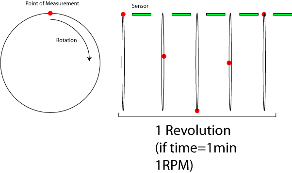
Because the wheel is turning and the sensor is fixed, using a mechanical switch where there is contact every rotation will not work very well. For example, the mechanical switch will cause friction every rotation. Also, maintaining perfect distance between the wheel and the switch will be difficult. Instead, there are two common ways of detecting rotation that do not require contact between the sensor and the wheel–optically and magnetically. Due to my own personal familiarity with magnetic circuits, as well as the expense of using an optical system and concerns about the functionality of that system in ambient light, I have decided to pursue magnetic sensing.
Sensing Changes in Magnetic Fields
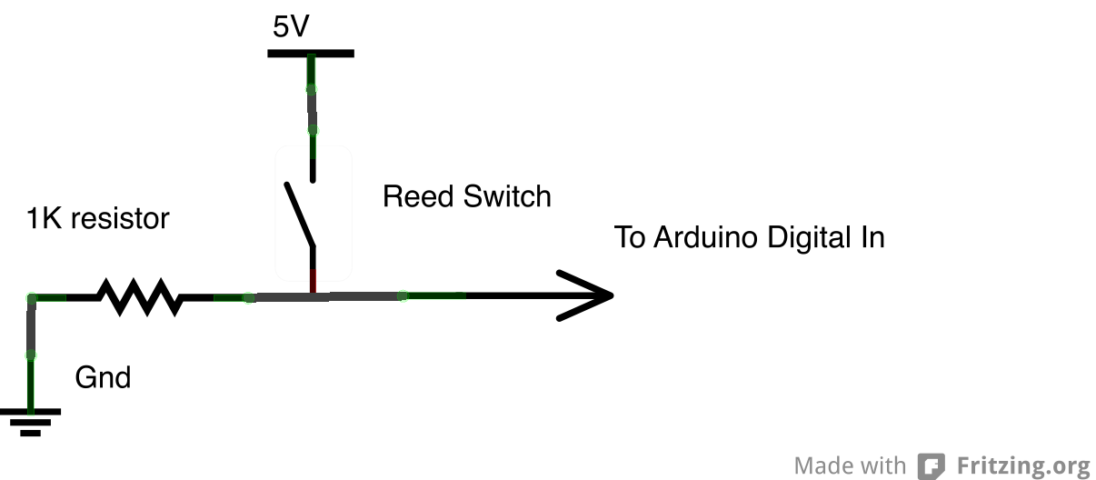
To construct a tachometer using a magnet, you attach the magnet to the wheel, and attach a sensor to the fork (at a fixed position). As the magnet passes by the sensor, it triggers a switch that allows you to count the number of revolutions over a period of time. There are two types of sensors that accomplish this function: reed switches and Hall effect sensors. The reed switch is a simple switch that is closed (or opened) using a magnet.
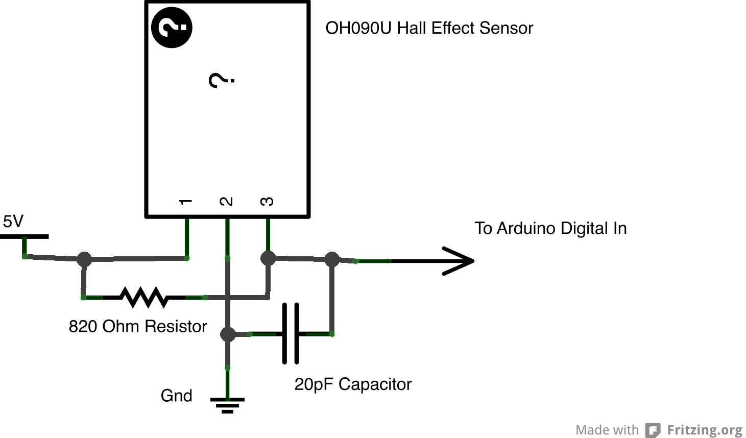
The Hall effect sensor converts changes in magnetic fields to analog voltage. The mystery of how the Hall effect actually works from a scientific standpoint goes beyond my level of understanding as a musician/tinkerer, but for our purposes the sensor functions like a digital switch. (Fritzing, which I used to make the schematic below does not have a built-in part for a Hall Effect sensor, so I am using the “mystery” part)
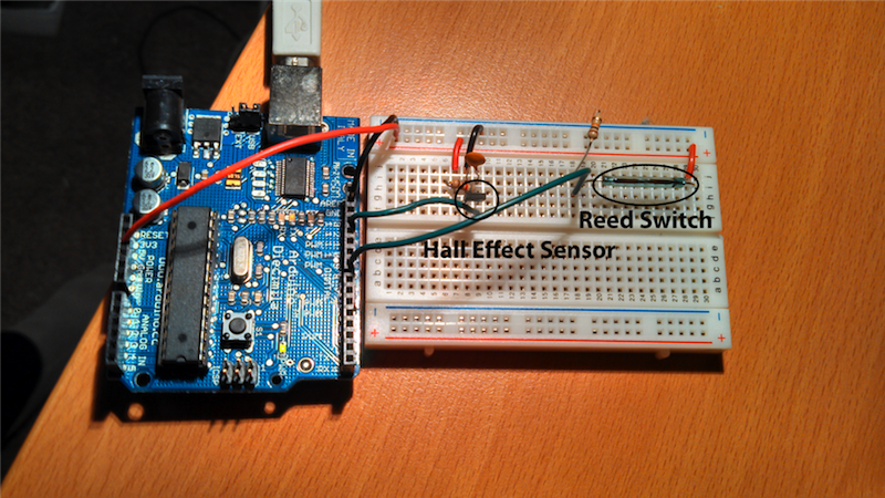
Testing
I tested both the reed switch (ORD-229-2530) and the Hall effect sensor (OH090U) with two types of magnets: 1/4″x1/16″ N42 neodymium magnet and 1/2″ x 3/16″ Ceramic Disc Magnet. I hooked both up to a simple sketch on the Arduino so I could see when the switches were open/closed. Neither magnet worked very well with the reed switch unless I was basically touching the switch (conclusion: I would need stronger magnets). Both magnets worked with the Hall effect sensor. The neodymium magnet consistently triggered the switch 1/4″ from the sensor and the ceramic magnet worked 3/8″ from the sensor. I am not sure what kind of sensing distance we will need for the rear wheel of the bike, however if these distances are too small, a stronger/larger magnet should work. My fellow Movable Partiers are working on getting their hands on some magnets from reclaimed bike computers, which hopefully will work well.
Next Steps
The goal of these preliminary tests was to make sure I could actually build the circuit and get it to work. The next step is to hook it up to a bicycle and make sure we can get an accurate count of rotations. The physical connection to the bicycle represents one challenge that should be figured out sooner rather than later. For the electronics, we will probably need to implement some kind of edge detection code on the Arduino to make sure that we only get one “trigger” every time the magnet passes the sensor. Once this has been accomplished, I will need to program a sketch on the Arduino that allows us to transmit the data to the computer, probably into Max.
Sonic Outcomes
While I enjoy designing and building hardware interfaces that allow interaction between the physical world/computer, I always (try to) keep in mind that the goal of these technologies is to provide meaningful interaction for audience participants. This step of “mapping” is the most critical and most often gets shortchanged due to time constraints. Therefore, it is important to think about the types of mapping we would like to use in parallel with designing/building the system. The most obvious relationship between the rotation of the rear wheel of the bike and music would be to convert RPMs to BPMs. In this paradigm, the speed of the rear wheel would control the speed of playback. Since there will be three bikes, it will be important to think about how the three data streams can work with each other. One idea involves each bike controlling the tempo of a particular track of a song–therefore the parts will only align when everyone is biking at the same speed.

7 Comments
Pingback: Movable Parts » Redirecting the Flow of Power
Pingback: beingwendyhsu.info » Redirecting the Flow of Power
Pingback: Movable Parts » Workshop #2: Sensors & Arduino Microcontrollers
Pingback: Rear Wheel Tachometer using arduino -Use Arduino for Projects